One of my friends and I decided we would build a self-balancing robot for our engineering expo. In our group, I was known as the guy with the steadiest hand and the cleanest solder joints, so the PCB responsibility naturally landed on me. We could have gone with an easy off-the-shelf controller setup, but we wanted to build our own board from scratch.
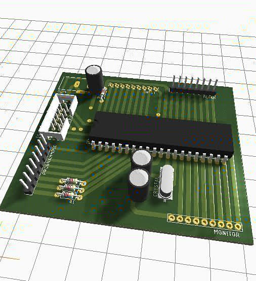
The heart of the board was the ATmega32A. Around it, I started placing everything it needed to run properly: a 16 MHz crystal with capacitors, reset circuit, voltage regulation, decoupling capacitors near VCC/AVCC, and headers for programming plus motor driver and sensor connections. I remember spending hours in Eagle CAD moving components by tiny amounts just to keep the routing clean and practical for manual fabrication.
That design phase was also shaped by reality: in Pokhara, we basically had one electronics shop we could count on. So every design decision had a second question attached to it, “Can we actually find this component here?” If the answer was no, I had to adjust the board.
Once the layout looked right, we printed the PCB track on glossy paper and got ready for the old-school process. No fancy PCB service, no CNC machine, no shortcuts.
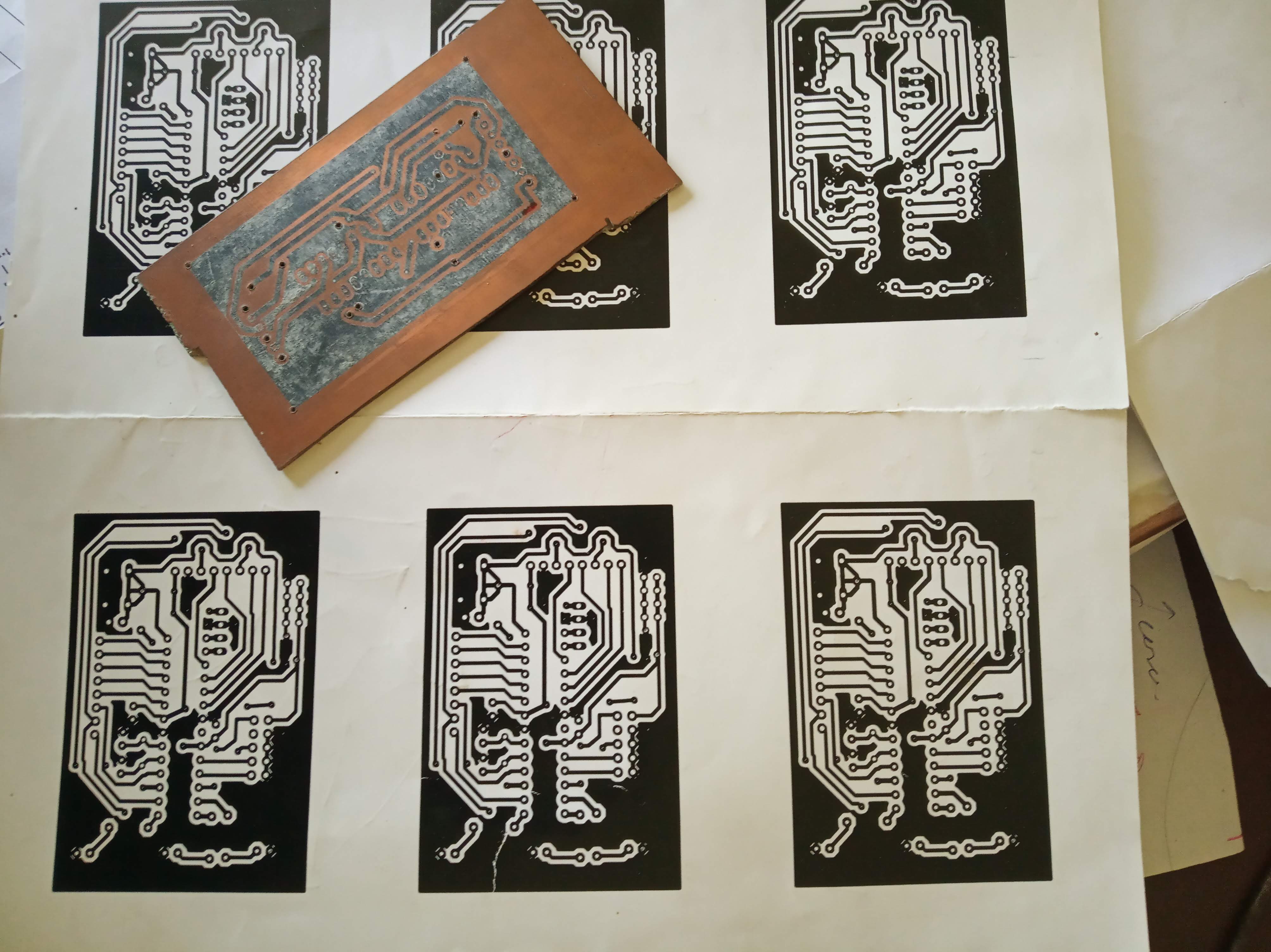
Then came the part that felt more like workshop craft than classroom electronics. We cleaned the copper board, pressed the paper onto it with a hand iron, and prayed the toner transfer would come out clean. Some tracks came out perfect, some needed touch-up by hand. After that, we dropped it into ferric chloride for etching, what I used to saying “itching” back then in the lab.
When the copper dissolved from the unwanted areas, we washed the board, dried it, and started hand drilling each hole one by one. That was the most patience-testing part. A small slip could ruin a pad, and then everything had to be repaired manually.
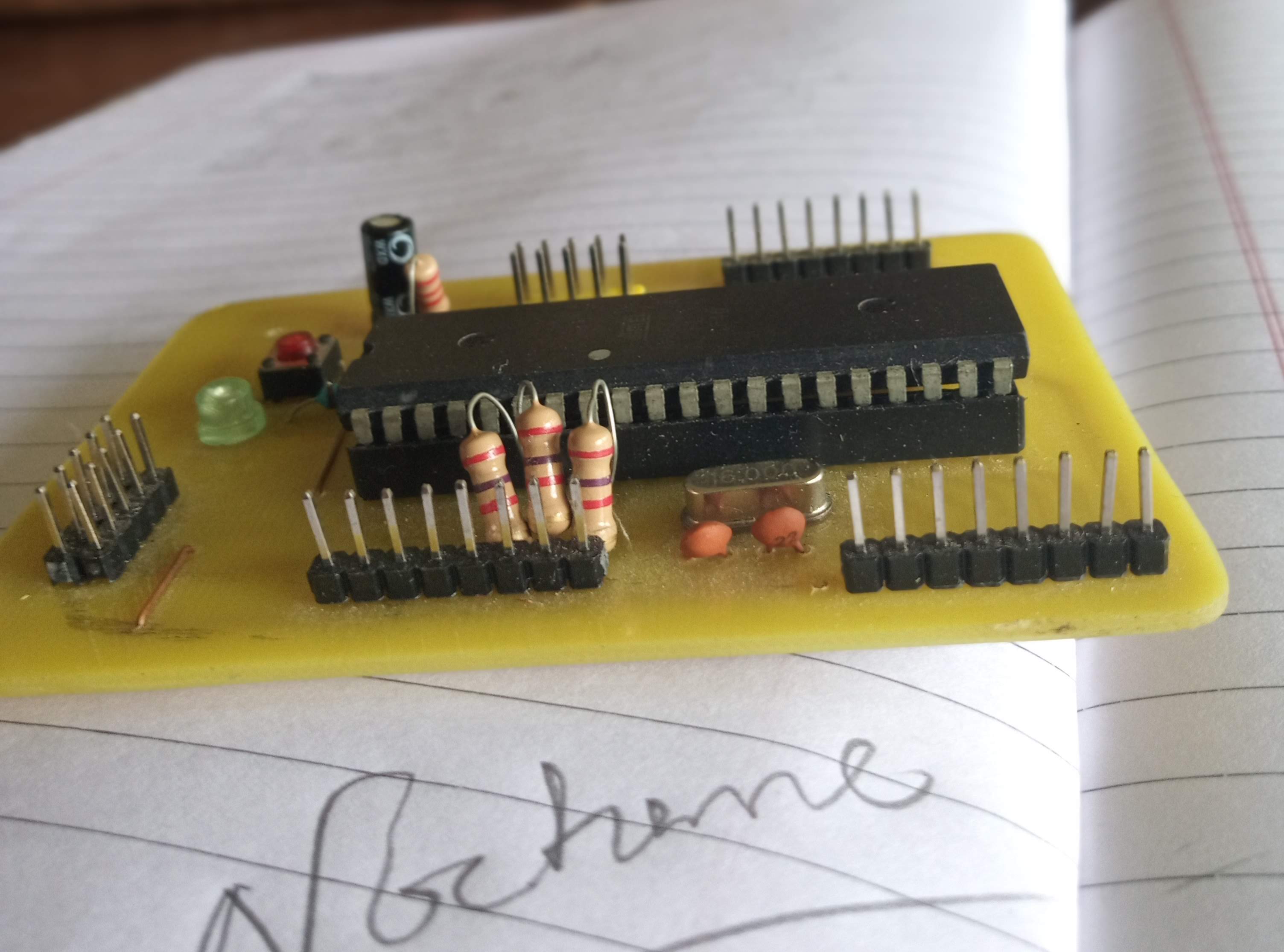
After drilling came soldering, continuity checks, and fixing tiny mistakes we had not noticed earlier. Slowly, it stopped looking like a chemistry experiment and started looking like a real controller board.
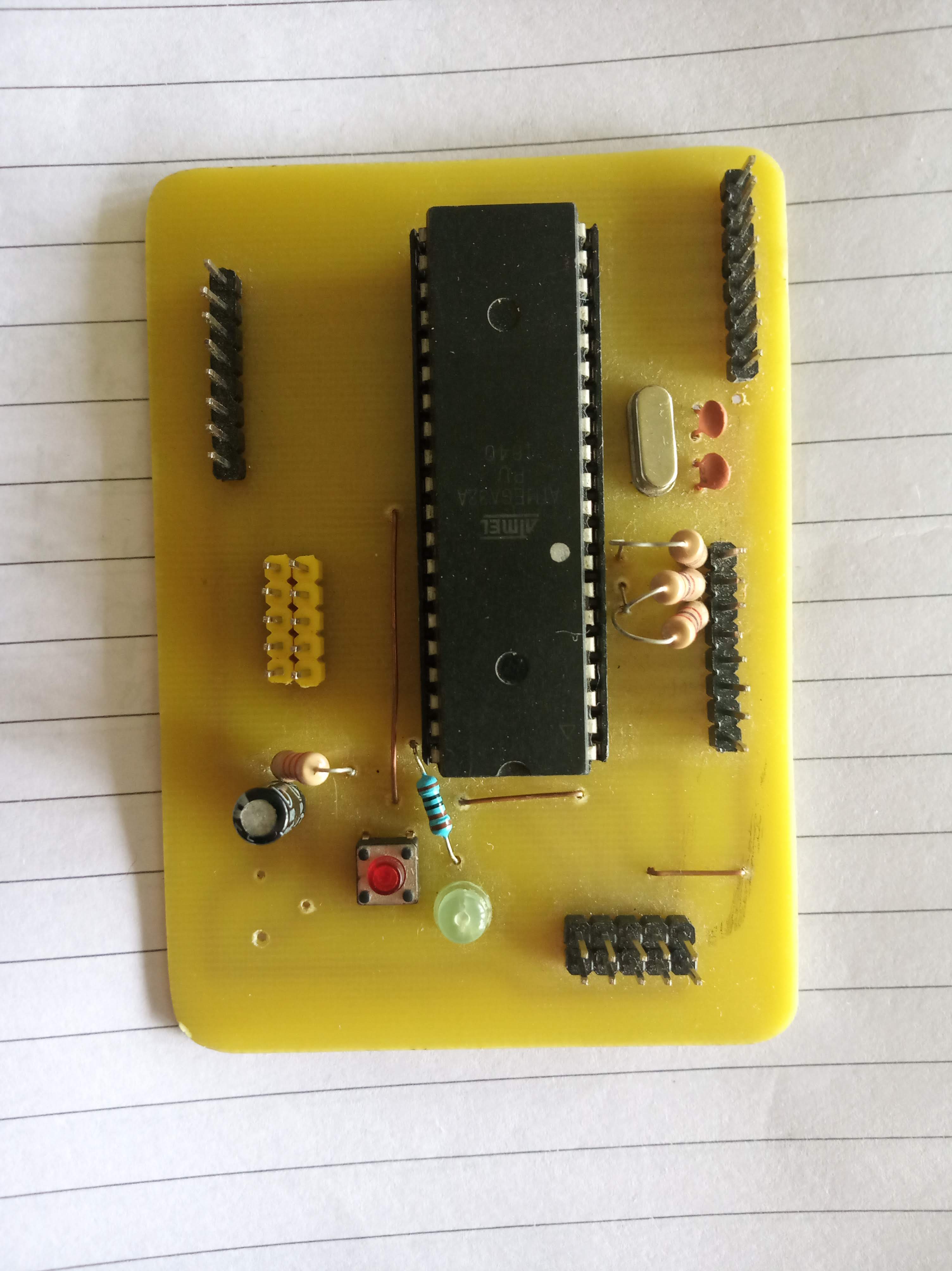
When we finally mounted it into the self-balancing robot setup, the difference was immediate. Compared to temporary breadboard wiring, this felt solid and dependable. The robot still needed tuning, but now we had a clean brain at the center of it.
Looking back, that board taught me more than just Eagle CAD. It taught me how hardware is not only about design on screen, but also about hands, heat, smell of etching solution, local component availability, and patience.