What Is It?
A fully handbuilt digital clock that does more than just tell time. Built around an ATmega328 microcontroller, the display cycles through three readings on a four-digit seven-segment panel: the current time, ambient temperature, and live sound intensity from a microphone.
No off-the-shelf clock module. Every piece of the circuit and every line of firmware was put together from scratch.
Demo
Hardware
| Component | Role |
|---|---|
| ATmega328 | Main microcontroller (Arduino-compatible) |
| DS1307 RTC module | Keeps accurate time over I²C |
| LM35 temperature sensor | Analog temperature readings |
| Microphone module | Captures ambient sound intensity |
| 4-digit 7-segment display | Output for all three readings |
What Is a 7-Segment Display?
A seven-segment display is one of the simplest ways to show numbers electronically. It has seven individually controllable LED segments arranged in a figure-eight pattern, each labeled a through g. By lighting different combinations, you can represent every digit 0–9.

Here is the display in its gloriously naked form, before the rest of the clock grew around it. The LED bulbs used here were lent to me by a friend, which is basically how this project qualified as both electronics and social networking.
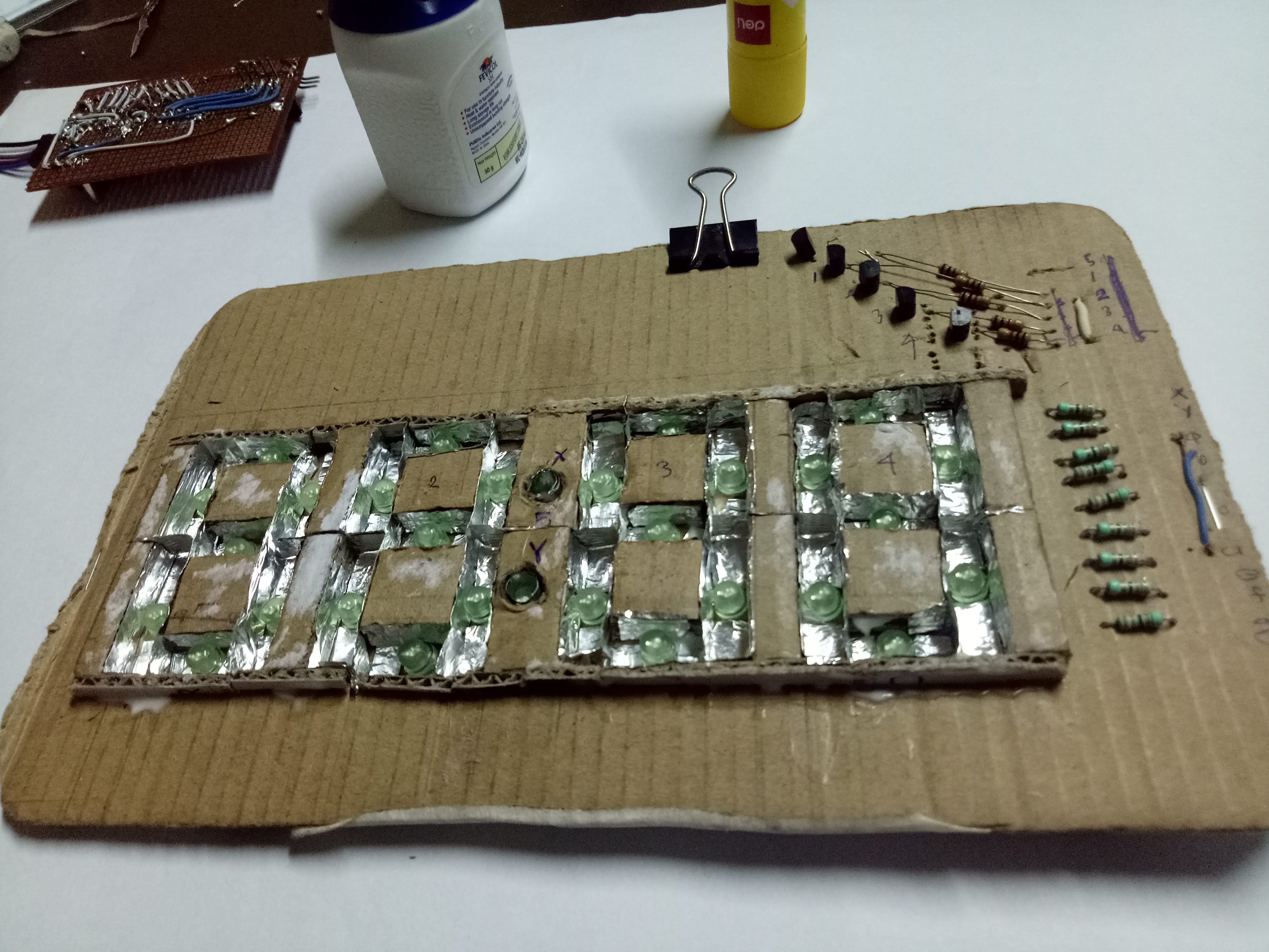
To show four digits (like 12:34), four of these units sit side by side. Driving all 28 segments individually would need 28 pins, so instead the firmware multiplexes: it activates one digit at a time in rapid succession (~1 kHz), fast enough that the eye perceives all four as simultaneously lit.


Temperature Display
Beyond the clock, the display also shows ambient temperature using an LM35 analog sensor. The LM35 outputs 10 mV per °C directly, no calibration formula needed. The ATmega’s ADC reads the voltage, converts it to degrees, and the firmware pushes it onto the same four-digit panel.
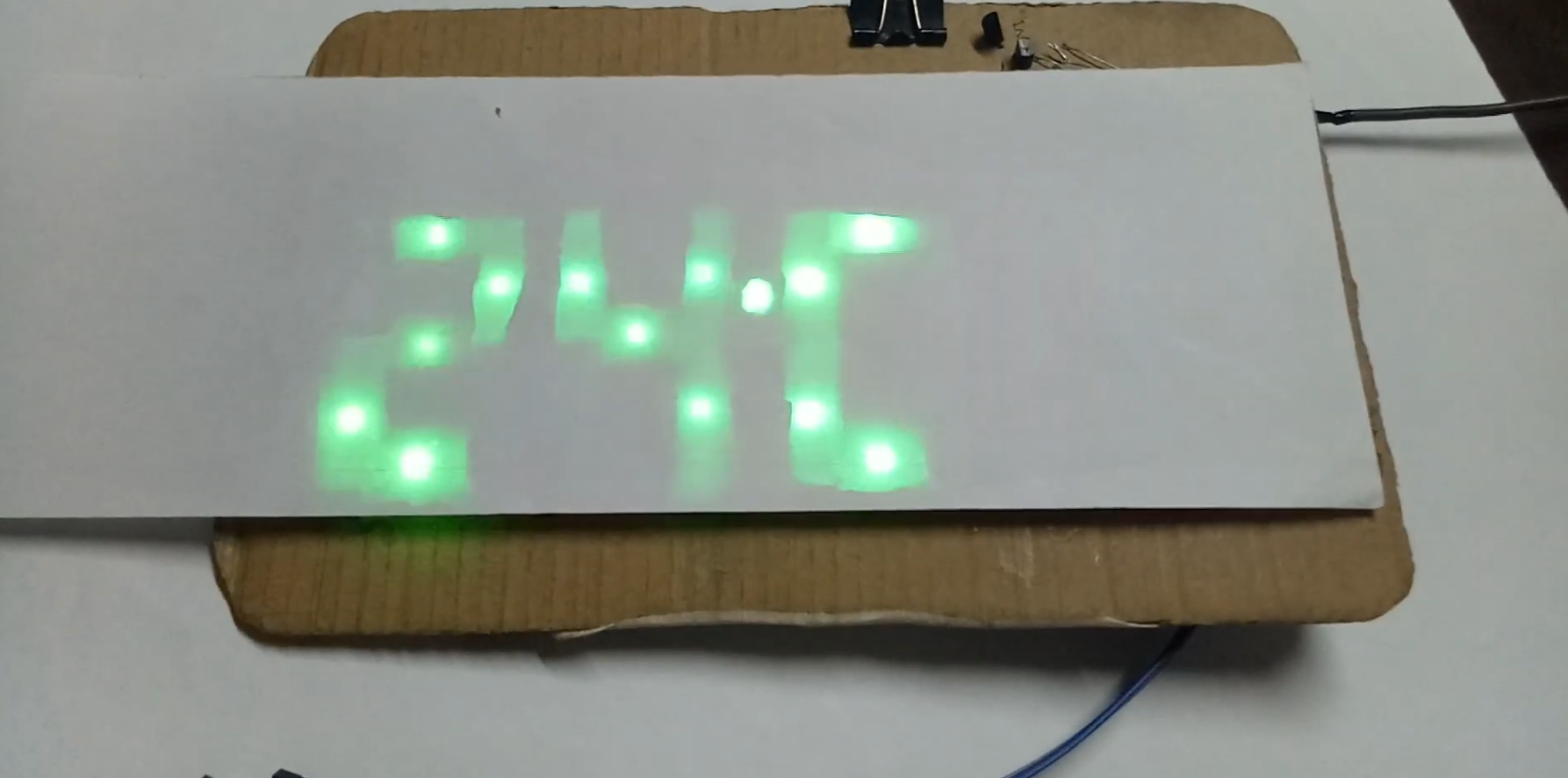
The photo above shows the display reading 24°C. The same four segments that show 12:34 a moment earlier now show 24°C. One panel, multiple modes.
Auto-Dimming at Night
One subtle feature: the clock automatically dims itself when the room gets dark.
A light-dependent sensor on pin A1 continuously feeds ambient brightness into the ADC. The firmware compares the reading against a threshold of 750 (out of 1023):
lux = analogRead(A1);

if (lux < 750) {
    digitalWrite(8, HIGH);  // dark → dim the display
} else {
    digitalWrite(8, LOW);   // bright → full brightness
}
Pin 8 drives the display brightness circuit. When lux drops below 750 (roughly when a room light is switched off), the display dims so it doesn’t blast light at you while you’re trying to sleep. When ambient light comes back up, it restores to full brightness automatically.
How It Works
The firmware is split into focused modules:
digitalClockSketch: reads the DS1307 over I²C and drives the 7-segment display with multiplexing to show HH:MM.displayTemperature: samples the LM35 analog output, converts the ADC reading to °C, and pushes it to the display.senseLight: reads the microphone module’s analog output and maps it to a 0–9999 intensity scale.fixDS: utility sketch for setting and verifying the DS1307 RTC time.
Each module was developed and tested independently before being integrated. The display multiplexes all four digits at a rate fast enough to appear solid to the eye.
What I Learned
This was one of my earliest hardware projects, and it taught me fundamentals that no tutorial fully captures:
- Multiplexing: getting the timing right matters. Too slow and you see individual digits strobing.
- I²C on bare metal: talking to the DS1307 directly made me understand the wire protocol rather than hiding behind a library.
- ADC noise: the LM35 and microphone readings are noisy straight off the pin. Even simple averaging makes a visible difference in the displayed values.
- Scope-driven debugging: when the display shows garbage, printf debugging doesn’t help. Learning to read a logic analyzer output was a turning point.